


TRIOL AT24 line UH
Place an order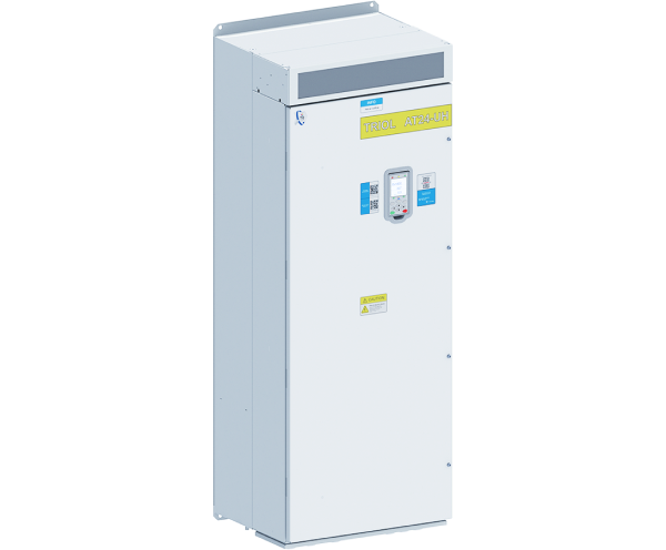
Distinctive benefits
Enclosure
IP55
-40 ºC…+50 ºC
Operating temperature
Removable graphic terminal
Operation without control terminal
Built-in
input fuses and DC link
Control type
Vector sensor (close-loop) and sensorless (open-loop) control
Encoders
3 different types of encoders supported
Motor parameters
auto-tuning of motor parameters with motor rotation and without it
Multi-tasking
Motor group control
Remote control terminal
Transient graphs
Macros
Quick start and the ability to exchange settings between VFDs
Control system
wide variety of expandable units for control system
About product
High-protective enclosure
Variable Frequency Drive Triol AT24 line UH is a universal solution for harsh operating conditions. Triol AT24 VFD line UH designed in a high-protective enclosure with a separate airflow cooling channel. Operation temperatures ranges from -40 ºC to +50 ºC (-40…+122 F) and allows using Triol AT24 VFD line UH for outdoor installation.
Wide range of implemetation
Triol AT24 VFD line UH is optionally equipped with a removable wireless control graphic terminal with induction supply. It is possible to control several VFDs. Triol AT24 VFD line UH is designed to control pumps, HVAC systems, exhausters, compressors, conveyors, crushers, mixers, grinders, mills. Various additional units for VFD control system extend abilities of process control. Setting up and controlling the AT24 UH is easy due to the use of: Wi-Fi adapter with step-by-step Triol Wizard via smartphone, Service software Triol Drive for PC, Remote control terminal with transient graphs
Specifications
| Input |
|
|---|---|
| Input voltage, V | 3х380 / 3х480/ 3×690 (-15 % …+10 %) |
| Input frequency, Hz | 50 / 60 (-5 %…+5 %) |
|
Output |
|
| Output current, A | 8.8 … 800 |
| Output frequency, Hz | 0.5…400 |
| Frequency resolution, Hz | 0.1 |
| Acceleration / deceleration time, s | 1 …4000 |
| Overcurrent characteristics | 150 % of rated value for 60 sec |
| Efficiency, % | >97 |
|
Motor control |
|
| Control methods | V/f (volts-per-hertz) (5 reference point) sensorless vector control (open-loop) sensor vector control (close-loop) |
| PWM frequency, kHz | 2…10 |
| Speed range | 1:100 in open-loop system 1:1000 in closed-loop system |
| Speed accuracy (static) | ±10% of motor nominal slip in open-loop system ±0.1 % of rated speed in close-loop system |
| Torque accuracy | ±10% in open-loop system ± 5 % in close-loop system |
| Braking | By frequency Coasting |
| Acceleration / deceleration types | S-curve, linear (3 reference points) |
|
Interface |
|
| Terminal | Removable graphic terminal with induction power |
| Light alarm | “Ready”; “Run”;” Fault”, “Control channel” |
| Push buttons | “Start”; “Stop”; “Program”, navigation keys |
|
Control signals |
|
| Customer supply | 10 V DC, up to 30 mA 24 V DC, up to 150 mA |
| Number of discrete inputs | 8 |
| Discrete inputs | 1 Dl Emergency Stop 8 Dl programmable |
| Discrete inputs type | 24 V |
| Sensor input | 1 PTC sensor (switching at a resistance of 3 kOhm / 1.8) |
| Number of relay outputs | 4 |
| Relay outputs type | 250 V, 3.5 A |
| Number of analog inputs | 2 |
| Analog inputs | Programmable 0…10 V / 0…5 mA / 4…20 mA |
| Number of analog outputs | 1 |
| Analog outputs | Programmable 0…10 V / 0…5 mA / 4…20 mA |
|
Communication |
|
| Physical Interface | 2 wire RS-485 for Modbus |
| Communication protocols | Modbus RTU |
| Frame transmission | 115200 bps by default 1200 -250000 bps |
| Data format | 8 bits, 1 stop bit, no parity |
| Number of addresses | 1…255 for Modbus |
| Access | Slave |
|
Protection |
|
| Supply protections | Phase loss, phase sequence fault |
| Motor protections | Overcurrent
Overload Underload Phase loss Current unbalance Encoder open circuit Brake resistor open circuit |
| VFD protections | Overload, Overheating, DC-link undervoltage, DC-link overvoltage, Power switch failure |
| Insulation | Galvanic isolation between power and user circuits |
| Insulation resistance | > 1 MQ |
|
Configuration |
|
| Input line chlnput fuses (characteristic gG) | Up to 55 kW: not available. From 75 kW: built-in |
| DC-choke | Up to 11 kW: option, built-in. From 15 kW: built-in |
| Braking IGBT-chopper | Up to 11 kW: built-in. From 15 kW: option, built-in |
| Input EMC-filter (C2) | Option, built-in |
| Coated PCB (3C3) | Option |
| Quick fuses (characteristic aR) | Option, built-in |
|
Optional equipment |
|
| Input line choke | Option, outdoor, by request |
| Input passive harmonic filter | Option, outdoor, by request |
| Braking resistors | Option, outdoor, by request |
| Output sine filter | Option, outdoor, by request |
| Output dV/dt filter | Option, outdoor, by request |
|
Operating conditions |
|
| Operating conditions | Indoor, no caustic and volatile air, no dust |
| Operating temperature | -40…+50 °C (-40…+122 F) |
| Storage temperature | -50…+60 °C (-58…+140 F) |
| Relative humidity, % | from 5 to 90 non condensing |
| Altitude, m | up to 1000 m – rated power above 1000 m – with reduced power |
|
Construction |
|
| Protection degree of Enclosure | IP55 |
| Cabinet material | Steel |
| Cooling | Forced air |
| Noise level, @ 1 m, dB(A) | <75 |
| Installation | Wall mounting |
| Maintenance | One-side |
| Cable entry | BottomFF |
Functions
Start / stop / reverse of motor with set acceleration and deceleration rates
- Motor speed and torque control
- Auto-tuning of motor parameters (with rotation and without)
- PID-controller
- 2-wire control
- 3-wire control
- Automatic restart
- “Catch on the fly” mode
- Motor group control
- Operation by calendar
- Energy and electricity meters
- Encoders supported – incremental, absolute, sine/cosine
- Accelerated passing of resonant frequencies (3 ranges)
- Recording the last 32 reasons of failures